SOLVED! Parasitic battery drain

Mike534x

Original poster
Member
Apr 9, 2012
935
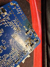
I'm thinking this interface may be bad, before even connecting it to the radio the interface was already warm to the touch as if it was powered on. Re-checked all the wiring connections, and its wired just like I did with the Trailblazer's radio I installed using the same setup.

PAC Interface Installed: 0.60
PAC Interface Removed: 0.15

This is just the interface itself WITHOUT the radio connected and receiving power.

Best Buy has the PAC Module in-stock, same exact model. I'm considering running over and grabbing it and seeing if the "new" off the shelf one has the same issue. If it does, then it looks like I'll need to look at an entirely different interface to use then.
 
  • Like
Reactions: Mooseman

Mike534x

Original poster
Member
Apr 9, 2012
935
Update time;

New PAC Interface has been installed. Biggest change noted was that it stayed cool to the touch while connected, without the radio hooked up. Barely felt warm after connecting the radio, and leaving it keyed on.

With the ammeter hooked up, the draw after key on/doors open/without waiting for the modules to sleep was hovering between 0.18-0.25. 3 hours have passed since installing it/last checking, and the current draw is hovering between 0.08-0.15.

Talk about a huge drop! I'm going to wait a few days before confirming this as fixed/solved.
As for the factory harness itself, there were no breaks or chaffing found. The factory tape that was wrapped around the harness was peeling away, so I took what I was able to reach off, and used some wiring harness tape to "renew" it. Didn't wrap up the new interface/radio harness wires, but I'll take care of it when I go to pull the climate control out to do my LED install on that.
 

mrrsm

Lifetime VIP Donor
Supporting Donor
Member
Oct 22, 2015
7,769
Tampa Bay Area
Interesting. I forgot about the phenomena of "PTC" (Positive Thermal Coefficient) that always occurs in Copper Wire circuits with resistance enough to cause the temperature to rise either in the Module or in the Wiring Harnesses involved.

As you yourself have already documented on another occasion, this is a very useful way to *see* hidden warm Modules inside of Door Panels and Lift Gate Panels, as well as in complete Darkness with no ambient light to confuse the Viewer when searching for even the faintest of IR emitters:

This is from your own Thread on the topic... so that Camera can still prove useful in this situation:


For others interested in affordable versions:


Attachments

  • PARASITICTESTSWITCHINSTRUCTSFINAL.pdf
    164.9 KB · Views: 3
  • Forward-looking infrared - Wikipedia.pdf
    727.6 KB · Views: 3
  • Thermal radiation - Wikipedia.pdf
    1.5 MB · Views: 5
Last edited:

Mike534x

Original poster
Member
Apr 9, 2012
935
I got a bit curious, and opened up the interface. I think you'll find this interesting. It looks like the board experienced a short-circuit, noted by the discoloration. This location is right next to the MOSFET, and a what I believe is the regulator where the Yellow Constant 12v, Red ACC and Ground meet for both the radio, and where it pulls in the power from the factory harness.
 

Attachments

  • 20240419_214914.jpg
    20240419_214914.jpg
    895.8 KB · Views: 13
Last edited:

mrrsm

Lifetime VIP Donor
Supporting Donor
Member
Oct 22, 2015
7,769
Tampa Bay Area
Which Module or Component was this PCB inside of...?
 

Mooseman

Moderator
Dec 4, 2011
25,374
Ottawa, ON
I'm gonna go out on a limb here and call it solved. That PCB is sure enough evidence and the current draw is much better.
 

Mike534x

Original poster
Member
Apr 9, 2012
935
Which Module or Component was this PCB inside of...?

The PAC RP5-GM11 interface :yes:

It would definitely explain why the heat was centered around that area the moment the interface was receiving power from the factory connection.
 
  • Sad
Reactions: mrrsm

budwich

Member
Jun 16, 2013
2,059
kanata
rather interesting... especially how a somewhat expensive device like that provides basically no electrical spec for its operation ranges especially when considering the wide range of subtending components that could be wired to it.
 
  • Like
Reactions: mrrsm and Mike534x

Mooseman

Moderator
Dec 4, 2011
25,374
Ottawa, ON
Definitely not unheard of since it has happened to me a couple of times with Metra adapters where they wouldn't shut off. However surprised this happened with a PAC since I used them to replace the Metra. That was when I had the 02 TB and the 06 9-7x with Bose. For the current 07 TB non-Bose, I just use a cheap Scosche which has worked well for years.
 
  • Like
Reactions: mrrsm and Mike534x

Mike534x

Original poster
Member
Apr 9, 2012
935
This is a first for me, I've always been told PAC was the "go-to" for interfaces. I would've gone with a Crux unit but I haven't had much luck with them in the past, so I guess this would be a rare occurrence where it may have had a faulty soldering job, or component leaving the factory.

However, it does leave a sense of relief. Aside from killing the battery, my concern lies in what would've happened in the long term if it was left plugged in.
 
  • Like
  • Love
Reactions: Mooseman and mrrsm

AmpOverload

Member
Jul 10, 2023
121
USA
Watch this video with Mr. O:
He will describe the voltage drop across a fuse to check what circuit is pulling current. (hence saving the purchase of a DC ampmeter) He explains his methodology in tracing down the culprit circuit. Definitely worth your time.
Thanks for posting that video!

For those who watched that "Part I" video but didn't notice that "Part II" is now out, here it is:

'14 Chevy Impala - Battery Dies Overnight - Part II

Also, to have for future reference, I chased down a source of that "Fuse Voltage Drop Chart" that Eric uses in "Part I". I don't know if this is the original source, but the chart is downloadable for various fuse types here:
 

mrrsm

Lifetime VIP Donor
Supporting Donor
Member
Oct 22, 2015
7,769
Tampa Bay Area
I think @Blckshdw has saved that Volts vs. Amperage Chart in one of the FAQs as well... or in one of the other Key Parasitic Diagnostic Threads.

For anyone wanting to "Future Proof" themselves against the chances of developing any Parasitic Drains without prior experience and chooses to use Less Expensive Equipment that will STILL do the Job just as well as either the Snap-On Vantage MT2400 or the Later Model Snap-On Vantage PRO Graphing Multi-Meters...THIS Encouraging Technician shows How To Properly Set Up This Equipment and NOT wind up Destroying Your Gear from any Accidental Amperage Surges at or Above 10 Amps:

 
Last edited:
  • Like
Reactions: Redbeard

Forum Statistics

Threads
23,347
Posts
638,203
Members
18,554
Latest member
evenson1

Members Online