SOLVED! Parasitic battery drain

Mike534x

Original poster
Member
Apr 9, 2012
935
Figured this might be the best place to post this question! So the parasitic drain is sadly not gone. However, I noticed the negative braided ground had corroded away. Does this tie into the underhood fuse box, or attach somewhere else? I've got a new strap ordered along with some replacement wiring loom.

I suppose it's technically more of a parasitic drain, then a draw with how quickly it's depleting the battery.
 

Attachments

  • 20240331_063909.jpg
    20240331_063909.jpg
    830.1 KB · Views: 13
  • 20240331_063834.jpg
    20240331_063834.jpg
    418.1 KB · Views: 10
Last edited:

Mooseman

Moderator
Dec 4, 2011
25,374
Ottawa, ON
That looks like the one for the hood. If it's coming from the firewall, then that's likely it. Look for an eyelet near the hood hinge that's missing a wire. It's of no real consequence. IIRC, it's for static engine noise more than anything.
 
  • Like
Reactions: mrrsm

Mike534x

Original poster
Member
Apr 9, 2012
935
That looks like the one for the hood. If it's coming from the firewall, then that's likely it. Look for an eyelet near the hood hinge that's missing a wire. It's of no real consequence. IIRC, it's for static engine noise more than anything.

The part circled is where the broken end of that ground attaches to. I can see the one attached at the firewall, I'll need to peel off the rest of the loom and look to see where it all leads to. So it seems the search continues.
 

Attachments

  • 20240331_063909.jpg
    20240331_063909.jpg
    1.2 MB · Views: 11
  • Like
Reactions: mrrsm

mrrsm

Lifetime VIP Donor
Supporting Donor
Member
Oct 22, 2015
7,768
Tampa Bay Area
THAT particular Ground (Bonding Strap) may be the one needed to connect the underside of the Metal Skin of the Hood to the Firewall in order to prevent RFI (Radio Frequency Interference) from disrupting the normal Environmental RF Energies ...such as those created by a Fluorescent Overhead Lamp Ballast (High Frequency Transformer) for instance.

Look under the Hood areas within the reach of it when the Hood is either in the Opened or Closed Positions for the presence of a Broken off Metal Tang or a Fastener. The absence of this Bonding Strap being properly installed should NOT induce any sort of Parasitic Drain upon the Truck Battery.

Off Topic ...but involved in your RFH (Request For Help) mentioned above...

The Best ways for Diagnosing Low Amperage Drains are covered in several Parasitic Drains Threads here at GMTN or linked via a search either via Google or DuckDuckGo as shown below:

gmtnation parasitic drain


There should also be a comprehensive "How To Diagnose a Parasitic Draw or Drain" PDF that I penned which should be attached and available somewhere in the FAQ Listings as well.

But frankly, Mike... my concern is drawn to suggesting that you investigate the possible damage to your Under Hood Harnessing after observing what looks like artifacts of Rodents Gnawing upon the Plastic Harness Sheathing encircled in Red within THIS Close Up Image:

POSSIBLERODENTGNWDAMAGE.jpg
 
Last edited:

Mike534x

Original poster
Member
Apr 9, 2012
935
THAT particular Ground (Bonding Strap) may be the one needed to connect the underside of the Metal Skin of the Hood to the Firewall in order to prevent RFI (Radio Frequency Interference) from disrupting the normal Environmental RF Energies ...such as those created by a Fluorescent Overhead Lamp Ballast (High Frequency Transformer) for instance.

Look under the Hood areas within the reach of it when the Hood is either in the Opened or Closed Positions for the presence of a Broken off Metal Tang or a Fastener. The absence of this Bonding Strap being properly installed should NOT induce any sort of Parasitic Drain upon the Truck Battery.

Off Topic ...but involved in your RFH (Request For Help) mentioned above...

The Best ways for Diagnosing Low Amperage Drains are covered in several Parasitic Drains Threads here at GMTN or linked via a search either via Google or DuckDuckGo as shown below:

gmtnation parasitic drain


There should also be a comprehensive "How To Diagnose a Parasitic Draw or Drain" PDF that I penned which should be attached and available somewhere in the FAQ Listings as well.

But frankly, Mike... my concern is drawn to suggesting that you investigate the possible damage to your Under Hood Harnessing after observing what looks like artifacts of Rodents Gnawing upon the Plastic Harness Sheathing encircled in Red within THIS Close Up Image:

View attachment 111844

I appreciate the link @mrrsm ! I've been combing through so many old/new threads between here and TV trying to figure out where to go. I've tackled most of the "common" modules that were known to be issues to others experiencing this. Between using my multimeter, and mini-fuse tester buddy, I cannot for the life of me find a steady power draw between the front + rear fuse box. The only lead I've had was my radio pulling .03 amps from the rear, and that's it. So I'm beginning to wonder if maybe my PCM/BCM is the likely culprit.

That section of the wiring loom was caused by me, I tried to gingerly peel back the loom, but the midwest weather has made it brittle, and it was just crumbling on me. But thats the ground cable going from the firewall to the no longer attached portion on the hood.
 
  • Like
Reactions: mrrsm

mrrsm

Lifetime VIP Donor
Supporting Donor
Member
Oct 22, 2015
7,768
Tampa Bay Area
Damn... Mike... I TOTALLY missed Post #22 from @Mooseman and your comments in Post #23 as well, making my diatribe in Post #23 completely redundant. It can be deleted.
 

Mike534x

Original poster
Member
Apr 9, 2012
935
Damn... Mike... I TOTALLY missed Post #22 from @Mooseman and your comments in Post #23 as well, making my diatribe in Post #23 completely redundant. It can be deleted.
No worries at all! The insight was still very helpful! Part of me was hoping that the strap was the issue but since it's not then the search is still on sadly.
 
  • Like
Reactions: mrrsm

Mike534x

Original poster
Member
Apr 9, 2012
935
Still sorting out the parasitic draw, but I may be on the right track now...hopefully!

After not finding anything out of the ordinary with the front and rear fuses, I moved into relays. I noticed that the draw slowed when removing relay #60 (on the 5.3), and the ignition/starter fuses. Part of the drain I have corrected was from the Dorman Ignition Switch (I'll make a separate thread about that one). I would assume the Powertrain relay is what provides power to the PCM/BCM? If so, I was pondering if those were maybe going bad that is.....

I found green crusties (as Eric O would say) poking it's ugly head out of the negative cable that grounds to the body. My assumption at this point, is the various modules aren't fully going to sleep and because the ground isn't making full proper contact they're staying partially awake.
 

Attachments

  • 20240406_213143.jpg
    20240406_213143.jpg
    373.6 KB · Views: 7
  • Like
Reactions: mrrsm

mrrsm

Lifetime VIP Donor
Supporting Donor
Member
Oct 22, 2015
7,768
Tampa Bay Area
Mike... These Two Threads Piggy-Back towards the IPC being THE Culprit in both instances of Parasitic Drain:


Mike534x

Original poster
Member
Apr 9, 2012
935
Mike... These Two Threads Piggy-Back towards the IPC being THE Culprit in both instances of Parasitic Drain:


IPC's been ruled out, I removed the cluster as well as the fuse and its still there. Even sent it out for a full rebuild to be on the safe side.

Checked the grounds going from the negative terminal, wheel one has some corrosion, as does the one leading to the engine block. Not sure if that is playing a part in it. Unfortunately the V8 negative cable is unobtainium, so I may need to make a new cable.
 
Last edited:
  • Like
Reactions: mrrsm

Mike534x

Original poster
Member
Apr 9, 2012
935
  • Like
Reactions: mrrsm

mrrsm

Lifetime VIP Donor
Supporting Donor
Member
Oct 22, 2015
7,768
Tampa Bay Area
That's my Thinking as well... Because the Green Meanies (Cupric Oxide) can migrate almost the entire length of the Cable Strands and increase Electrical Resistance, elevate the Amperage Draw and make everything Electrical behave poorly. If you want to be conservative, try removing the Corrosion locally to those connections using CRC Battery Terminal Cleaner to clean it all up and then reattach the Grounds with a small amount of Dielectric Grease in between the Eyelets and Fasteners:


61-vaDE654L._AC_SL1499_.jpg

I know it seems counterintuitive... but most of these problems occur whenever two or three dissimilar pieces of Metal come into direct contact with each other and set up conditions of Ion Transfers known as "Galvanic Corrosion"... EXACTLY like ... A Battery (or *PILE*).

Alternatively, its a toss up between what happens when the Saline Road Salt battles its way upwards from the road underneath the SUV ...and the Battery Acid (H2SO4) as Sulfuric Acid leaching downwards from around Cracked Seals at the Battery Posts or Side Terminals and or the Plastic Encasement as well. These two chemical Electrolytes seriously speed things along to destroy the metals in direct contact with them as well

When tightened down properly, the Bolt(s) passing into the Engine Block and the Firewall should have sufficient electrical conductivity so the presence of the DE Grease will NOT cause any Poor Grounding Events. This is the main reason why Folks should NOT use Stainless Steel Bolts to hold Headers and Exhaust Manifolds onto Aluminum Engine Head Exhaust Ports.

The Galvanic Action there will turn the Thread Lines into Aluminum Oxide Powder. Anybody familiar with the Marine Environment and the use of Copper Bottom and attaching Sacrificial Zinc Blocks upon Steel Hull Ships knows how extreme this Ionic Action can become around a Permanently Salty Environment. This is why Brass and Stainless Steel are preferred as well versus Aluminum and Mild, Unprotected Steel and Sheet Metal. While Copper is even a Better Electrical Conductor than GOLD...once it combines with Oxygen to form Cupric Oxide...it becomes...(Wait for it...) A Dielectric!

Which Metal is the Best Conductor of Electricity?​

This list of electric conductivity includes alloys as well as pure elements. Because the size and shape of a substance affect its conductivity, the list assumes all samples are the same size. Here are the basic types of metals and some common alloys in order of best to worst conductors of electricity:

From best to worst (equally sized):
  1. Silver
  2. Copper
  3. Gold
  4. Aluminum
  5. Zinc
  6. Nickel
  7. Brass
  8. Bronze
  9. Iron
  10. Platinum
  11. Steel
  12. Lead
  13. Stainless Steel
Source:


Last edited:

Mooseman

Moderator
Dec 4, 2011
25,374
Ottawa, ON
I have moved these posts to its own thread as it was getting really off topic in the grounds info thread.
 

Mike534x

Original poster
Member
Apr 9, 2012
935
I have moved these posts to its own thread as it was getting really off topic in the grounds info thread.
Sorry about that Moose! Thanks for moving it!

@mrrsm I don't see the harm in ordering a can of the CRC battery cleaner, and give it a few sprays along with a bit of cleaning to the grounds and see what that'll do. Both cables are on order, and will be arriving Wednesday as well.


Info on the truck, and what's been done tested for those who stumbled upon this thread.

2005 GMC Envoy Denali, SWB, with the 5.3

- Old AGM Battery was replaced due to no longer holding a charge.

- Alternator has been replaced, old one was defective and would not hold a steady 13v+ charge during the drive cycle.

- New DEKA Intimidator AGM Battery.

- Swapped out the "dinky" GM Battery terminal nubs for 3/8" brass terminal connectors. (Couldn't get battery tender clamps to get a good bite)

What I've tested;

- Removed the "remote starter" brain, no difference in battery drain.

- Disconnected On- Star Module, no change.

- Disconnected aftermarket head unit.

- Tested Front and Rear Fuse box with a mini fuse tester, found nothing aside from a .01 draw from the radio fuse, and the draw from the HVAC module (which is supposedly normal according to GMs tech bulletin)

- Bose AMP fuse removed, center console wiring harness disconnected and checked for pinched wiring. Nothing found.

- 3 different ignition switches (tested using the original, the grey backed switch installed 4 years ago) and the new Dorman switch. This includes testing the gearing position to see if it was due to a misaligned gear keeping the ignition on. No change.

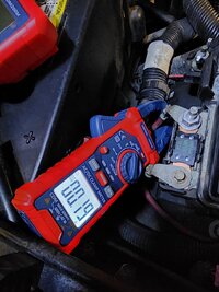
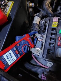
Pulling the Powertrain relay, and both 40 amp ignition fuses made a noticeable difference.

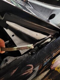
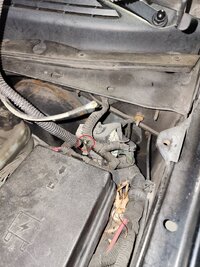
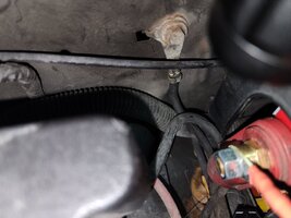
Conclusion so far, based on the recent pics is that the grounds are causing the BCM/PCM to stay partially awake or my BCM may be the culprit. While installing the new battery cables, I'm going to recheck the other grounds and see what I find.
 

mrrsm

Lifetime VIP Donor
Supporting Donor
Member
Oct 22, 2015
7,768
Tampa Bay Area
And since you (Mike) already know of these issues, but others arriving may not, having the Two Fuse Box Layouts for BOTH the I-6 LL8 and V8 Engines in BOTH the Under-Hood AND the Under Rear Seat Fuse Block Layouts might prove helpful in seeing any differences between the two... here they are.

Note that these images were extracted from the 2005 GMC Envoy Owner's Manual available at GMT Nation... and via THIS Link:

https://www.manualslib.com/download/61408/Gmc-2005-Gmc-Envoy.html

The OM does have additional information regarding the behavior of the Electrical System during KOEO that is also worth knowing BEFORE beginning any Parasitic Draw Testing. Knowing which Circuits are "HOT AT ALL TIMES" can also aid in finding STGs (Shorts To Ground) that will be easier to check off if they are highlighted on all of these Fuse Box Layouts dependent upon which Sub-Models are involved.

Checking the Green -N- Gold Flex Cable attaching the BCM Module to the Fuse Block in the Under-Seat location for Damage and the Rear Lift Gate for the Thru The Grommet locations for Breaks in the Wires might also help to eliminate them as locations for any STGs.

RAPINFO.jpgBATTERYRUNDOWN.jpgFUSEBLOCK.jpgL6FUSEBLOCK.jpgV8FUSEBLOCK.jpgGMCENVOYFUSES1.jpgGMCENVOYFUSES2.jpgGMCENVOYFUSES3.jpgGMCENVOYFUSES4.jpgGMCENVOYREARFUSES1.jpgGMCENVOYREARFUSES2.jpgGMCENVOYXLREARFUSES32.jpgGMCENVOYXLREARFUSES4.jpgGMCENVOYXLREARFUSES5.jpg
 
Last edited:
  • Love
Reactions: Mike534x

Mike534x

Original poster
Member
Apr 9, 2012
935
@mrrsm You are amazing for posting the differences in the fuse boxes! I'm hoping once it's said and done, and I find the culprit this could prove to be useful FAQ for those who may have a similar issue in the future!

Update as of April 10th;

Both new Positive and Negative battery terminals have arrived, and looked identical to the ones in the truck now. All proper attachments seem to be the correct length, and I shouldn't have any issues installing them this weekend hopefully...*knock on wood*

Anywho, I pulled down the rubber isolator boot and inspected the wiring at the tailgate for any pinched, or damaged wires for the LGM. All is well, and I'm receiving power when testing each one so that rules it out (on top of pulling the fuses the prior day to test).

Before pulling every BCM fuse, the recorded voltage was at 12.6v, after a full day of being untouched it was at 12.4v. Which still seems a bit excessive. Considering that's a rough 10% drop. While inside the Envoy, I noticed that the Ambient Air Temp Sensor (inside the 2" speaker on the Driver B-Pillar) was turning on without the doors being opened. That's rather odd, as from my research, it should only run during Key "ON", and when upon opening the door and shutting off once the dome lights come off. I ordered a new AC Delco replacement, and installed it. So we shall see by tomorrow night what the next recorded voltage drop is. I know the sensor is fed by the HVAC-B fuse, that leads to the climate control unit.

So knowing this, could my issue actually be the climate control (auto) unit that's in the truck? I'm going to yoink the HVAC fuses next. But I can happily say the BCM did not contribute or change the power draw. But for now, the hunt continues!
 

mrrsm

Lifetime VIP Donor
Supporting Donor
Member
Oct 22, 2015
7,768
Tampa Bay Area
Mike...NP, Brother ... THIS Dude (Brandon from Jarhead Diagnostics) gets right to the point with his suggestions and helpful hints with his GEAR for Testing for an STG (Short To Ground) by LOADING THE CIRCUIT AT THE FUSE BLOCK in place of the Fuse using a Protected In-line Test Lamp along with an In-Line Audible GIZMO to alert you that:

"A Short To Ground... is YET to be Found".


Equipment Used:

https://www.jarheaddiag.com/shop/p/sh...
https://www.jarheaddiag.com/shop/p/hi...

9B33D1FC-D31F-42E7-A291-45C8CEFAB61F.jpeg426B403F-1D02-46B4-9B85-A7D264236E19.jpegD13126E1-A508-47C6-9431-FEC0D3AC150D.jpegimage0+(1).jpegIMG_1061.jpg

THIS GM Color Coding for Wiring PDF may help to run down the "Hot AT All Times" Circuits:
 

Attachments

  • GM_Wiring_Colours.pdf
    50.4 KB · Views: 3
Last edited:
  • Like
Reactions: Redbeard

Mike534x

Original poster
Member
Apr 9, 2012
935
I may need to look into that!

So update time. No luck. I feel like I made zero progress these last few weeks. However I am curious. Have the blower motor control modules been known to cause a drain? The original was replaced a few years ago after it melted at the connector, and died. That was replaced with a newer one, and the blower motor stopped working completely last year and I replaced it with one by TYC.

So I'm contemplating climbing underneath and unplugging the blower motor to see if it's running ever so slightly with the key off.
 
Last edited:

budwich

Member
Jun 16, 2013
2,059
kanata
I ordered a new AC Delco replacement, and installed it. So we shall see by tomorrow night what the next recorded voltage drop is. I know the sensor is fed by the HVAC-B fuse, that leads to the climate control unit.
OK... what was the result of this? Is the temp sensor still turning on?
 

Mike534x

Original poster
Member
Apr 9, 2012
935
OK... what was the result of this? Is the temp sensor still turning on?

The sensor shuts off 30 seconds after key off, and does not come back on like it did before.
 
  • Like
Reactions: budwich

budwich

Member
Jun 16, 2013
2,059
kanata
Maybe I missed something along the way. Can explain how you are testing your "drain" as I am not sure watching voltage Is the best method. I know it is quite a task trying to isolate things with "wake ups" and "sleeps" happening. Have you thought about investing in a clamp-o-meter to help with things as it seems like you have bought / done a lot. The meter might not be "tre accurate" but it might give some immediate views of changes when fuses are pulled.... especially if you are looking for a "drain". Do you actually know what your "drain" is at "sleep"?
 
Last edited:

Mooseman

Moderator
Dec 4, 2011
25,374
Ottawa, ON
Have the blower motor control modules been known to cause a drain?
Yes however it is quite evident with a running blower motor after key off but worth investigating. Doing an elimination parasitic test should be able to dispel or find the actual drain circuit.
 
  • Like
Reactions: mrrsm

Mike534x

Original poster
Member
Apr 9, 2012
935
Yes however it is quite evident with a running blower motor after key off but worth investigating. Doing an elimination parasitic test should be able to dispel or find the actual drain circuit.

Figured there was no harm in asking, I'm yanking every fuse/relay tonight afterwork and going through the slow painful process of inserting each one until I come across the culprit (hopefully). Before doing so, I may just go ahead and yank both fuse boxes and inspect the tracers for any corrosion or possible hair line cracks/fractures.
 
  • Like
Reactions: mrrsm

Mooseman

Moderator
Dec 4, 2011
25,374
Ottawa, ON
You can't do it that way. When you put power back on to a module, it will draw until it goes back to sleep. You have to connect an ammeter between the battery and cable terminal, wait for everything to go back to sleep and then pull one fuse at a time until you see the draw drop.


The first fuse you should disconnect is the 125A maxi fuse to eliminate or implicate the rear fuse box. If it doesn't drop, then it's in the front box so then pull one fuse at a time there. If it is something in the rear, put the maxi fuse back, wait for everything to go back to sleep and then pull one fuse at a time in the rear box and watch which one drops.
 

mrrsm

Lifetime VIP Donor
Supporting Donor
Member
Oct 22, 2015
7,768
Tampa Bay Area
Precisely... And these sort of harnesses make it possible to do the passive testing WITHOUT losing the existing PCM and internal memory set-ups once the Battery Terminal is unfastened and separated from the Battery Terminal...and MEASURE the Amperage Draw in between ...in ALL of its Parasitically Fine Grained Silent Glory:

Like these...


PARASITICDRAINTESTER1.jpgPARASITICDRAINTESTER2.jpgPARASITICDRAINTESTER3.jpg
P
 
Last edited:
  • Like
Reactions: Mike534x

Redbeard

Member
Jan 26, 2013
3,484
Watch this video with Mr. O:
He will describe the voltage drop across a fuse to check what circuit is pulling current. (hence saving the purchase of a DC ampmeter) He explains his methodology in tracing down the culprit circuit. Definitely worth your time.
 

Mike534x

Original poster
Member
Apr 9, 2012
935
Appreciate the helpful videos, and links! I do have a parasitic drain tester I ordered a few days ago from Lisle coming along with a ammeter. AstroAI had one on sale for a reasonable price, that seemed to have very positive reviews from what I was reading. So between that, and following Eric O's advice for testing fuses, I'm hoping to make progress finally. I do feel the ammeter will be a huge help in tracking this sucker down.

Its sitting on the charger now, and I pulled the 125A Mega Fuse. With everything coming tomorrow afternoon/evening, I figured there's no harm in disconnecting the charger in the morning, and rechecking where its at when I get home from work. If the Tender is still reading full, along with the battery monitor then I know I can just strictly focus on the rear fuse box.

I should be able to get away with just flipping the door latch, to trick it into thinking the doors closed?
 

mrrsm

Lifetime VIP Donor
Supporting Donor
Member
Oct 22, 2015
7,768
Tampa Bay Area
And in another "How To Diagnose a Parasitic Draw"...this Home Mech Tech uses a similar set up with an identical Snap On Vantage Pro Graphing Multi-Meter to Eric "O" "s in Part 1 above (looking forward to Part 2) in order to Monitor (and Record) the situation for a necessary extended period of time while trying to isolate the Mysterious Amperage Draw.

The added information about using a Narrow Gauge Wire with a small enough Outside Diameter to encircle it with a Snap On Low Amp Clamp and NOT Risk a Fire should the Head Lights suddenly come one and Draw TOO Much Current by using a Small 10 Amp Circuit Breaker...is ALWAYS Top Of Mind for SAFETY in these types of situations:

 
Last edited:

Mike534x

Original poster
Member
Apr 9, 2012
935
Spent a good bit last night rewatching these videos, and several others. Battery was topped off by mostly by 10 PM last night. Waited an hour to recheck the resting voltage which was at 12.8v, woke up at 5 this morning for work and rechecked it again and it was 12.75v. Made a note of it on my phone, and will check it again around 6 this afternoon.

Already off to a better start, especially when the battery was down to 12.6-12.5v after 5 to 6 hours. So it's looking like my culprit is coming from whatever is being fed by the rear fusebox.

As always, I'll post a follow up tonight or this weekend once I start digging in. But at least this narrows down exactly where to focus my attention towards.
 

Mooseman

Moderator
Dec 4, 2011
25,374
Ottawa, ON
You could put the meter on the mega fuse and then do the fuse pull thing in the rear box. I'd still do a test from the battery with the mega fuse disconnected to be sure to eliminate the front box.
 
  • Like
Reactions: mrrsm

mrrsm

Lifetime VIP Donor
Supporting Donor
Member
Oct 22, 2015
7,768
Tampa Bay Area
While teaching many of his Students over at Rosedale College in Pennsylvania... Paul "Scanner" Danner often remarks for them to:

(1) Raise the Hood... and Touch NOTHING.
(2) Look around while thinking, "Points Of Contact...Heat...and Vibration".
(3) Study the Area...From the Outside... IN...Look for signs of Rodents.
(4) Look CLOSELY at the Wire Bundle Harnesses for their POINTS OF CONTACT.
(5) Set Up your Basic Diagnostic Equipment (Scope & Scanner) and THEN Move Things.
(6) Watch the Screens for *Glitching* and Zone in on those areas with a Bright Flash-Light.
(7) Lift Up the Harnesses and LOOK UNDER EACH CLOSELY FOR SIGNS OF GREEN CORROSION.

POINTSOFCONTACTHEATNVIBRATION1.jpgPOINTSOFCONTACTHEATNVIBRATION2.jpgPOINTSOFCONTACTHEATNVIBRATION3.jpgPOINTSOFCONTACTHEATNVIBRATION4.jpgPOINTSOFCONTACTHEATNVIBRATION5.jpgPOINTSOFCONTACTHEATNVIBRATION6.jpgPOINTSOFCONTACTHEATNVIBRATION7.jpgPOINTSOFCONTACTHEATNVIBRATION8.jpgPOINTSOFCONTACTHEATNVIBRATION9.jpgPOINTSOFCONTACTHEATNVIBRATION10.jpg


In one of his Videos..the Test Vehicle was a 2005 Chevrolet Equinox that had been invaded by Mice and Rats. They Urinated (Highly Corrosive) and Defecated on these areas involved (With Serious (Fatal 40% of the Time) HANTA Virus Risks from making incidental contact with BOTH Airborne Particle Inhalation and via Hands to Eyes and Mouth Contact.)

NEVERTOUCHDEADANIMALSWITHBAREHANDS.jpg
NEVERTOUCHDEADANIMALSWITHBAREHANDS1.jpg

This Vehicle suffered from a combination of Bad Motor Mounts. coupled with Poorly Isolated Sub-Harnessing at the Fuse Box, coupled with Rodents using the Harnesses as Roadways covered in Greasy Urine and Salt Crystals and walking damage done to the Harness Sheaths from their Claw Tracts. All of these events conspired to Prevent this Vehicle from Starting due to ONE WIRE Shorting Out inside of the Bundle.

So look around for similar artifacts...and Beware of what Paul did HERE by handling a Dead, Half-Eaten Baby Bird laying on a pile of Rodent Feces by picking it up... with his Bare Hands. If you see similar things like the Nesting Materials and the Red Highlighted "Mouse Grease" as illustrated in these images with the Red Arrows... Use M11 Nitrile Gloves and an N-95 Mask and Avoid Using Compressed Air to Dust Off anything under there. Look around very carefully for similar causes for that Parasitic Draw.
 
Last edited:
  • Like
Reactions: Redbeard

Mike534x

Original poster
Member
Apr 9, 2012
935
So I've got everything setup to fully test tomorrow. I went out to get an idea of how the ammeter is going to work, and I noticed its a bit of a tight squeeze getting the clamp around the negative cable...especially when trying to position it into a good spot.


While gingerly pulling back the loom to get more "slack" from the negative cable, I was curious if I can still get an accurate reading if I take the ammeter and clamp it so its getting a reading off the red wire that leads to the megafuse? If not I'll stick to the negative on the battery. However, I did notice that the ammeter was picking up a 0.58-0.60 draw when it was clamped around that cable. Did a test run, and pulled just the HVAC, and LGM fuses one by one while looking over to see if the meter picked up any changes which it didn't until I pulled the 15A Radio fuse, that caused the draw to drop to 0.19 which was where it stayed.
 

Attachments

  • 20240418_200725.jpg
    20240418_200725.jpg
    405.2 KB · Views: 3
  • 20240418_200659.jpg
    20240418_200659.jpg
    478.9 KB · Views: 3

mrrsm

Lifetime VIP Donor
Supporting Donor
Member
Oct 22, 2015
7,768
Tampa Bay Area
Bingo on The Radio... And Yes...you can use either the Battery Positive or the Battery Negative Cables... you would just have to invert the Clamp Jaws to get the Voltage Direction worked out if your input was being routed to an Oscilloscope Screen... and if not... Still be able to see the Small Screen activity on the Clamping Tool in plain sight. Pretty much any activity passing either way will register on the Ammeter... assuming it is sensitive enough to pick up VERY Low Amps.

Try Pulling The Radio from the Dash... and Give it "The Gentle Shake Test" if you hear ANYTHING moving around inside....well... eBay often carries Legacy GM Radios for not TOO Much Moolah... :>)

Look over those Connectors and Antennae insert areas for Wire Nicks, Pinches, Cuts or Corrosion. In the past, everything from "Dimes, Quarters and Bobby-Pins" to Lost Paper Clips have fallen out from shorting electrical contacts inside the CD Trays when being used by Kids and Drunk Adults playing "Slot Machines" with the Damned Things!
 
Last edited:

Mike534x

Original poster
Member
Apr 9, 2012
935
Bingo on The Radio... And Yes...you can use either the Battery Positive or the Battery Negative Cables... you would just have to invert the Clamp Jaws to get the Voltage Direction worked out if your input was being routed to an Oscilloscope Screen... and if not... Still be able to see the Small Screen activity on the Clamping Tool in plain sight. Pretty much any activity passing either way will register on the Ammeter... assuming it is sensitive enough to pick up VERY Low Amps.

Try Pulling The Radio from the Dash... and Give it "The Gentle Shake Test" if you hear ANYTHING moving around inside....well... eBay often carries Legacy GM Radios for not TOO Much Moolah... :>) Look over those Connectors and Antennae insert areas for Wire Nicks, Pinches, Cuts or Corrosion.

Excellent! So I can definitely get away with using the current location then?
Well good news and bad news, I still have the factory radio sitting on the shelf in the garage. What's in there currently is a Kenwood headunit, with a PAC RP5-GM11 module. I thought the old one was the issue, so I recently purchased this in the beginning of March to replace the "old" one. Unless my chances with a faulty module are high, and this one was defective as well which would be very interesting to know. But I'm just banging my head against the wall, wondering why the parasitic draw didn't rear its head when I yanked the radio + radio fuse the first time.

Though I guess that is the "fun" of chasing this suckers down I guess, never easy, but a royal pain. My next plan is honestly putting the OEM radio back in, and just seeing where she sits overnight and if the battery is still where it is now then I can at least confirm its most likely the Kenwood then.


budwich

Member
Jun 16, 2013
2,059
kanata
The radio might be "live" BUT it isn't necessarily pointing at a failure. I believe that the system utilizes the radio for notification / alert functions. Those maybe active because of what is happening on the data bus system causing the radio to be live / awake. You likely need to look at the data bus to determine what / if any modules are "disturbing " things that is waking the radio.... maybe. Your swap back to the old radio might help point to a radio issue but be prepared to look elsewhere if that doesn't happen.
 
Last edited:

Mooseman

Moderator
Dec 4, 2011
25,374
Ottawa, ON
It's not unheard of that radio interface modules can go bad and keep the power on.
 
  • Like
Reactions: mrrsm

Mike534x

Original poster
Member
Apr 9, 2012
935
I do recall seeing an older post here a few years back, of someone having a similar issue with a PAC module causing a drain as well. I'm just surprised that the replacement could be defective out of the box too.

I put the factory OEM touchscreen radio in, and will be checking the draw for a baseline to compare to what I was getting with the PAC + Kenwood installed. I've had issues with it before, but it has me wondering if it's the root cause. I'm pulling out the Pioneer unit I had originally installed to compare the readings. If the draw barely increases with that installed, I know it's the Kenwood causing it. I suppose if it goes up then I'll be able to confirm it's the interface, and if another doesn't solve it then it'll confirm that there is a module not going to sleep like @budwich suggested.
 

mrrsm

Lifetime VIP Donor
Supporting Donor
Member
Oct 22, 2015
7,768
Tampa Bay Area
If you do another R&R Swap of the Radio... While the Radio is removed... Look up the Connector Pin-Out Diagram(s) and then perform a Basic "Powers and And Grounds" Check on the related Wires, noting any Differences between "Key On ACC On" and "Key Off Engine Off" as well.

P.S. It won't Hurt to use a Bright Flashlight and a *Graduated Eye-Ball* to check for any incidental vibration wear-thru on the Radio Harnessing.
 
Last edited:
  • Like
Reactions: Redbeard

Forum Statistics

Threads
23,347
Posts
638,198
Members
18,553
Latest member
keithdm