P1280, P1271. P1275 SES and REP

mubai

Original poster
Member
Jan 5, 2012
321
Just got this code yesterday. I was able to clear the code then replicate the same. The code and light comes on after about 5-10 minutes of driving then with hard acceleration.

Just need some help with diagnostic steps. Does anyone have the schematics? I'd like to at least follow the lines and see if there's a short or loose connection any where.
 

djthumper

Administrator
Nov 20, 2011
14,955
North Las Vegas
Check the wiring hardness near the left upper control arm. There have been a couple of reports of the wires being rubbed. Also check the connections on the PCM.
 

mubai

Original poster
Member
Jan 5, 2012
321
Where is the harness located? Are you referring to inside the hood or inside wheel well? I did take a peek around but didn't see any issues in both areas.


djthumper said:
Check the wiring hardness near the left upper control arm. There have been a couple of reports of the wires being rubbed. Also check the connections on the PCM.
 

MAY03LT

Member
Nov 18, 2011
3,422
Delmarva
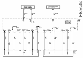
mubaiapp.png

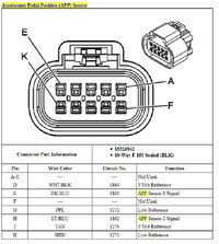
mubai2app.jpg

I can say that I've never seen a 1280 without a 1275. For 1280, "The APP sensor 2 voltage is less than 0.13 volts or more than 4.87 volts."

So with key on/engine off, the light blue wire at the APP connector (with APP connector still plugged in) should be between those two values. IIRC on APP2 the volts will be close to 4v with pedal released and go down around 1v with pedal on the floor. As the pedal is slowly pushed, the volts should slowly and smoothly go down. If the voltage is nutty or goes open the APP might be bad.

There's another way to test APP on the bench (with a meter on ohms) but I got burned by that before so now I use volts.
 

mubai

Original poster
Member
Jan 5, 2012
321
Thanks MAY03LT.

While i was driving, I originally had a 1271 and 1280. I erased the codes and full power was restored. Next day, today, I removed the APP connector and checked for codes it threw 71, 75 and 80. Erased everything plugged it bsck in then 1280 was the only code. Erased again and drove around for a bit and no codes.

Ill replicate the scenario to get the SES and REP, then go through the test. It will be on Friday, since I'll be in SF this week.

Also thinking to permanently attaching my code reader to the dash. I seem to use it more often than 4LO. Ha!
 

mubai

Original poster
Member
Jan 5, 2012
321
Today, while driving leisurely I got the SES and REP again. Code P1271. I tried doing the testing procedure as MAY03LT explained it but I'm still not sure how to test. Am I supposed remove the sheath around the blue wire? Where do I ground the black lead?

I went and looked under the hood to see if I can see any loose wires and I think I found one. I cleaned off the bolt, sanded down the body around the clip and used another split washer and tightened down the bolt. I cleared the code and drove around for a bit, hard acceleration a couple of times and no codes. I'm not 100% convinced I solved the issue, but we will see over time.

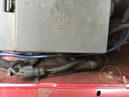
Drive's side view, front of truck to the left.

ground wire envoy.jpg
 
  • Like
Reactions: Sib

mubai

Original poster
Member
Jan 5, 2012
321
Can an admin add 1271 and 1275 in the topic subject? Might be easier for others to find.
 

mubai

Original poster
Member
Jan 5, 2012
321
OK, it's been 9 days since I last posted and happy to report all is good. No SES/REP. This issue was completely user error, I took out the ground wire when I went to replace the power steering fluid line. Never tightened it back down like it should have been.

Thanks to all for helping to diagnose the issue: mechanical visual inspection and electrical testing were the right things to do. :yes:
 

mubai

Original poster
Member
Jan 5, 2012
321
Ugh! I got the SES/REP lights P1271, no hard acceleration just driving in a parking lot. I cleared the code and all was normal. Didn't feel like driving in limp mode back home.

MAY03LT - can you give me more details on how to check the voltage? Specifically, if I need to remove the sheath around the wires and possibly a suggestion to where I should ground?
 

MAY03LT

Member
Nov 18, 2011
3,422
Delmarva


This isn't the APP but this how I do it. This is backprobing which lets you test a live circuit while it's connected. The T-pin slides through the back of the connector at the pin that needs to be tested. So meter on dc volts, red on the APP wire, black on ground. They use those t-pins for sewing so the misses might have one somewhere. :cool: But if she doesn't, a small paper clip can work in a pinch.


There's a good ground at the flasher on this pin. You can see that there's enough room for the dmm lead so no t-pin required. I use the column bolts when I test the ignition switch. The bolts for the pedals are hit and miss IMO.

When you get the meter hooked up, turn the key on (engine off) and see your voltage with the pedal released. Slowly push the pedal to wide open and see if voltage goes crazy or OL on its way to fully pushed. You may have to do the test many times since this is an intermittent issue.

Also I'd do the same test for APP1 since when I originally posted the info I didn't know about the other code. The voltage will be inverted at APP2 - it will start high and go low with the pedal pushed.
 

mubai

Original poster
Member
Jan 5, 2012
321
Ha! You're right! The Mrs. does have the T pin, and in two sizes. BTW, she says, "Hi." I will try tomorrow after I get some alligator clips. Thanks!
 
  • Like
Reactions: MAY03LT and Mounce

MAY03LT

Member
Nov 18, 2011
3,422
Delmarva
The at-rest fluctuating of APP2 seems odd. I think we need something to compare to. My 03 has the same APP so I'll see what mine looks like tomorrow or saturday..
 
  • Like
Reactions: mubai and Mounce

Texan

Member
Jan 14, 2014
622
I am going to throw this idea out as a possibility.
Could this be related to the fan clutch electrical connector
wiring or the fan clutch? I think I saw this in another thread.
Can you try driving it with the fan disconnected, but do
not let it over heat.
 
  • Like
Reactions: MAY03LT

mubai

Original poster
Member
Jan 5, 2012
321
Thanks, I got invited to go watch the Shoprite LPGA, near AC tomorrow so I'll be there in the morning. I'll check my emails because Im obsessed with my phone. First step is admitting you have a problem. :smile:
The at-rest fluctuating of APP2 seems odd. I think we need something to compare to. My 03 has the same APP so I'll see what mine looks like tomorrow or saturday..

I am going to throw this idea out as a possibility.
Could this be related to the fan clutch electrical connector
wiring or the fan clutch? I think I saw this in another thread.
Can you try driving it with the fan disconnected, but do
not let it over heat.

Happy to try it, but what am I looking for? I went 8-9 days without the SES/REP coming on. If it was constantly on I would see the reason.
 

MAY03LT

Member
Nov 18, 2011
3,422
Delmarva
http://i150.photobucket.com/albums/s98/MAY03LT/th_apptest_zpsfaye1svs.mp4

So I tested my APP2 and the voltage was fluctuating while at rest. So that's ruled out.

Now comes the hard part - making it do it on demand. That's the only way you're gonna know for sure if its a bad pedal assembly. What Texan is saying is true, sometimes the fan clutch or its wiring will cause the 5v reference signal to go up to battery voltage. The 5v signal is shared between the TPS, APP, fan, A/C pressure sensor and FTP sensor.
 

mubai

Original poster
Member
Jan 5, 2012
321
Ok, that does help. It would've been more helpful if it didnt fluctuate. ;-)

Thanks again for doing the test, appreciate you going out of your way.
 

mubai

Original poster
Member
Jan 5, 2012
321
Got the P1271 and P1280 again, no real surprise. I'm going to perform the following checks (found on another forum):

Check the voltage with the ignition turned on (engine not running). With the meter set to read DC voltages, voltage should be between about 4.9 volts and 5.1 volts.
You check the voltage in 2 places.
(1) between the white/black wire and the purple wire
(2) between the tan wire and the brown wire. You can actually use either a digital or a needle meter to check voltages.
Then check the sensor resistance (there are 2 sensors) with the engine turned off and the meter set to read resistance.
You check the resistance in 4 places.
(1) Dark blue wire and white/black wire,
(2) dark blue wire and purple wire,
(3) Light blue wire and tan wire,
(4) Light blue wire and brown wire.
Here it doesn't matter which wire you connect to the red or black meter probe, just check the 2 wires in each step together. When you press the accelerator pedal down, the needle should move up or down smoothly, should not jump or hesitate at all, as that will generate the error code. You need a needle meter for this.
 

MAY03LT

Member
Nov 18, 2011
3,422
Delmarva
Do you have a way to read freeze frame data? That should show the APP readings when the fault occurred. If only APP2 went out of range (P1280) that would (in theory) rule out the 5v reference signal.

I may have missed this the first go around but according to the service info, P1280 should be diagnosed first. P1280 is listed as "The APP sensor 2 voltage is less than 0.13 volts or more than 4.87 volts." and P1271 is "The voltage difference between APP sensor 1 and APP sensor 2 exceeds a predetermined value." That would make sense if there is a problem with APP2 then it would set a fault for APP2 and then set APP1 and APP2 correlation.
 

mubai

Original poster
Member
Jan 5, 2012
321
I dont have a scan tool that would read freeze frame data.

I tested the APP1 and APP2 previously, I posted up the results in a previous post with YouTube links. Is that what you were talking about?
 

mubai

Original poster
Member
Jan 5, 2012
321
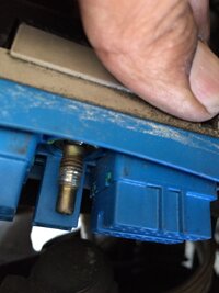
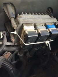
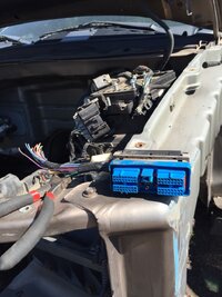
Maybe found the problem. This was loose. Wiggled it and threw all three codes, now where the hell do I find this screw?

ImageUploadedByTapatalk1437761756.909475.jpg
 

MAY03LT

Member
Nov 18, 2011
3,422
Delmarva
I thinks you're on to something since both APP circuits are in that connector.

I don't know who it was that had to repair one of the pcm connector bolts but I know that it has been done before.
 
  • Like
Reactions: mubai

mubai

Original poster
Member
Jan 5, 2012
321
$35 from dealership for the harness with bolt. Bolt not available separately.

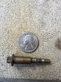
Here is the bolt:
ImageUploadedByTapatalk1437774183.423420.jpg

Here is my ghetto setup, until i find a bolt that works or spend $35 on the whole harness.
ImageUploadedByTapatalk1437774209.232913.jpg
 

Mooseman

Moderator
Dec 4, 2011
25,462
Ottawa, ON
You could jack one from a junker if you have a pick-a-part nearby. But that's if the bolt hole is undamaged in the PCM.

Can fix almost anything with zip ties. That and duct tape :biggrin:
 
  • Like
Reactions: mubai and Eric04

mubai

Original poster
Member
Jan 5, 2012
321
Thanks for the tip! I went to a U Pull nearby and found the part. $2 entrance fee and $1 for the part.

I must it admit it was quite a sad site to see the TBs and Envoys all mangled and their insides falling out.

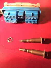
Anyway, I got the bolt out of the used PCM harness and installed it. Super tight fit now just like the other two harnesses. Lets hope this has fixed the problem. Ill run this truck exclusively between my wife and I for the next week and keep my other car in the garage.

ImageUploadedByTapatalk1437842154.386734.jpg

ImageUploadedByTapatalk1437842166.939509.jpg

ImageUploadedByTapatalk1437842180.062358.jpg
 
  • Like
Reactions: Mounce and MAY03LT

mubai

Original poster
Member
Jan 5, 2012
321
Funniest thing about this problem is that I haven't read one thread where the pedal sensor is actually the problem.
 

Mooseman

Moderator
Dec 4, 2011
25,462
Ottawa, ON
mubai said:
I must it admit it was quite a sad site to see the TBs and Envoys all mangled and their insides falling out.
Just like organ donors, these machines have bravely given their lives so others may live. :quiverlips: :sadcry: :hail:
 

Forum Statistics

Threads
23,387
Posts
638,686
Members
18,592
Latest member
Chadla11

Members Online